Servo Motor Stator Core & Rotor Laminations
Why the Motor Stator Core Defines Servo System Performance
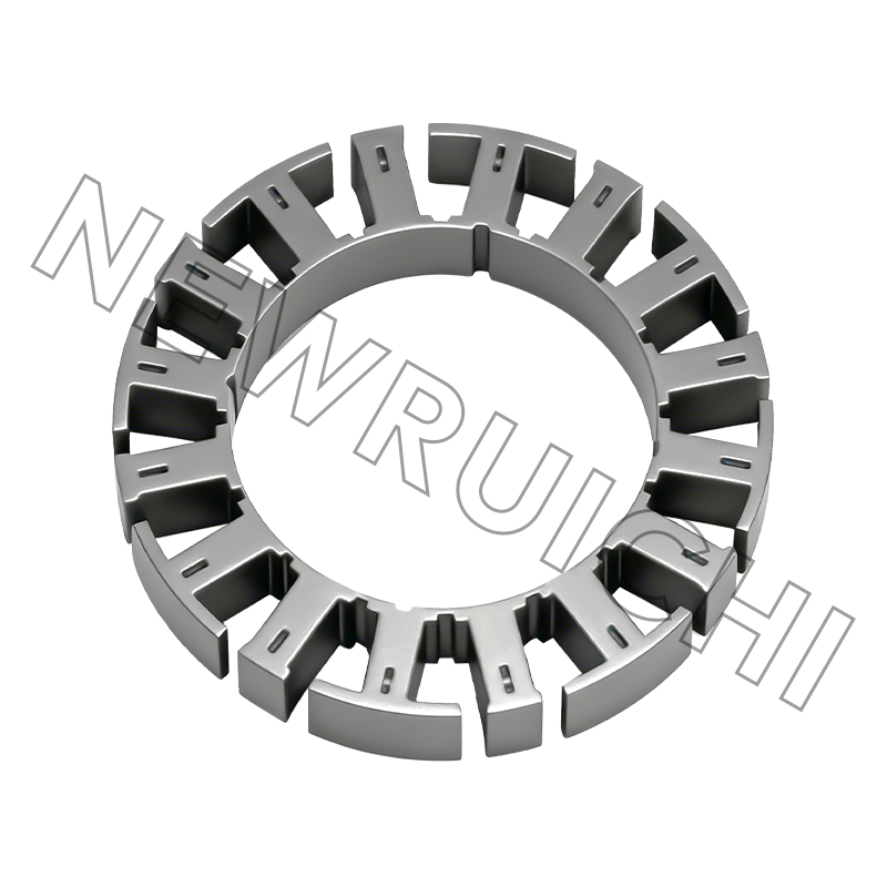
In any precision motion system, the servo motor functions as the actuating joint — translating electrical input into controlled mechanical output with millisecond-level responsiveness. At the center of that conversion process is the motor stator core: the fixed magnetic structure that generates the rotating electromagnetic field driving the rotor. Its geometry, material properties, and manufacturing precision collectively determine how efficiently and accurately that energy conversion takes place.
A well-designed stator core does more than conduct magnetic flux. It shapes the spatial distribution of that flux across the air gap, directly influencing torque linearity, back-EMF waveform quality, and the motor's ability to sustain precise position control across varying load conditions. In robotic arms, CNC machining centers, and high-cycle automated assembly lines — environments where positional accuracy is measured in micrometers and cycle times in milliseconds — the stator core is not a commodity component. It is a precision performance element.
Manufacturers who treat stator core selection and specification as an engineering decision rather than a procurement one consistently achieve better system-level outcomes: lower torque ripple, reduced thermal build-up, and longer operational intervals between maintenance cycles.
Material Selection: The Foundation of Low-Loss Magnetic Performance
The magnetic and electrical properties of the lamination material set an absolute ceiling on motor efficiency and dynamic response. For servo motor stator and rotor laminations, high-permeability silicon steel — typically non-oriented electrical steel with silicon content ranging from 2% to 3.5% — is the material of choice in precision servo applications.
Silicon alloying suppresses eddy current losses by increasing electrical resistivity, while high-permeability grades ensure that the magnetic circuit saturates at higher flux densities, allowing more torque output per unit of core volume. The key performance parameters to specify when sourcing lamination material include:
- Core loss (W/kg) — measured at specific flux density and frequency (e.g., 1.0 T at 50 Hz or 400 Hz for high-speed applications); lower core loss reduces thermal generation and improves efficiency at operating speed
- Relative permeability (μr) — higher permeability reduces the magnetomotive force required to achieve a given flux density, enabling more responsive torque generation
- Lamination thickness — thinner laminations (0.20 mm, 0.27 mm, 0.35 mm) reduce eddy current losses at higher electrical frequencies; the appropriate thickness depends on the motor's rated speed and control bandwidth
- Insulation coating — interlaminar insulation (typically C-5 or C-6 grade coating) prevents eddy currents from bridging between stacked laminations, maintaining the intended loss characteristics of the assembled core
For ultra-high-speed servo motors operating above 10,000 RPM, amorphous metal alloys or cobalt-iron grades may be specified in place of conventional silicon steel, offering substantially lower core loss at high frequencies at a corresponding cost premium.
Precision Stamping: How Manufacturing Process Drives Dimensional Consistency
The transition from raw electrical steel to finished servo motor stator and rotor laminations requires precision stamping technology capable of holding tight geometric tolerances across high-volume production runs. Dimensional inconsistency in laminations — variations in slot geometry, tooth width, or outer diameter — translates directly into magnetic asymmetry in the assembled core, producing harmonic distortion in the air gap flux and measurable increases in torque ripple.
Progressive die stamping is the dominant production method for servo motor laminations, offering the throughput and repeatability required for consistent quality at scale. Key dimensional parameters controlled during stamping include:
- Slot geometry tolerance — slot width and depth directly affect winding fill factor and flux path reluctance; typical tolerance targets for servo-grade laminations are ±0.02 mm or tighter
- Burr height control — excessive burrs from the stamping shear zone increase effective lamination thickness, compromise insulation integrity, and create stress concentrations that elevate hysteresis loss; burr height is typically controlled to ≤0.05 mm
- Flatness and camber — out-of-flat laminations create stacking non-uniformity that introduces rotor eccentricity and vibration at operating speed; flatness deviation is typically specified within 0.1 mm per 100 mm of lamination diameter
- Inner and outer diameter concentricity — critical for maintaining uniform air gap around the rotor circumference, which directly governs the spatial harmonic content of the air gap flux density waveform
Smooth edges achieved through controlled die clearance and regular die maintenance also contribute to mechanical balance during high-speed rotation, reducing the vibration excitation forces that would otherwise translate into audible noise and accelerated bearing wear.
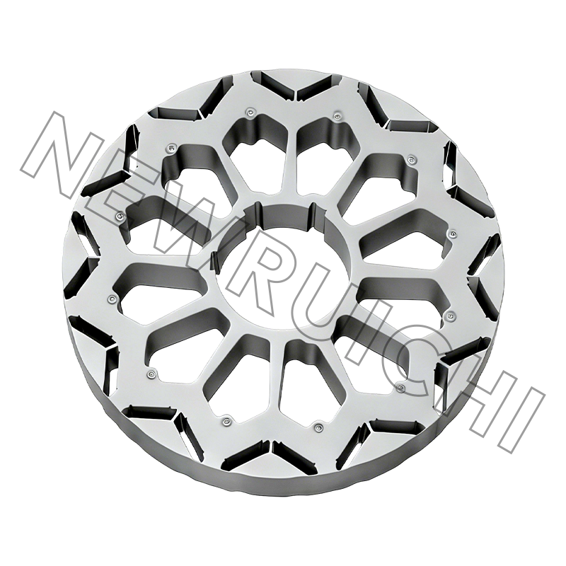
Stator Rotor Core Design: Pole–Slot Matching and Magnetic Circuit Optimization
The stator rotor core configuration — the combination of stator slot count, rotor pole count, and their geometric relationship — is the primary design variable governing torque ripple magnitude, cogging torque, and winding inductance in servo motors. Getting this combination right is not simply a matter of selecting a high pole count or a large slot number; it requires systematic evaluation of the harmonic interactions between the stator MMF distribution and the rotor flux pattern.
Common pole–slot combinations used in servo motor designs and their performance characteristics are summarized below:
| Pole / Slot Combination | Cogging Torque | Winding Factor | Typical Application |
|---|---|---|---|
| 8P / 12S | Low | 0.866 | General-purpose servo, robotics |
| 10P / 12S | Very low | 0.933 | High-precision positioning, direct drive |
| 6P / 9S | Medium | 0.866 | Compact servo, medical devices |
| 14P / 12S | Very low | 0.933 | Low-speed high-torque, collaborative robots |
Beyond pole–slot selection, auxiliary design features in the stator rotor core geometry — including stator slot skew, rotor magnet skew, and tooth tip chamfering — are applied to further attenuate cogging torque harmonics. These geometric refinements are implemented at the lamination stamping stage, making their accurate execution dependent on the same dimensional precision discussed in the previous section.
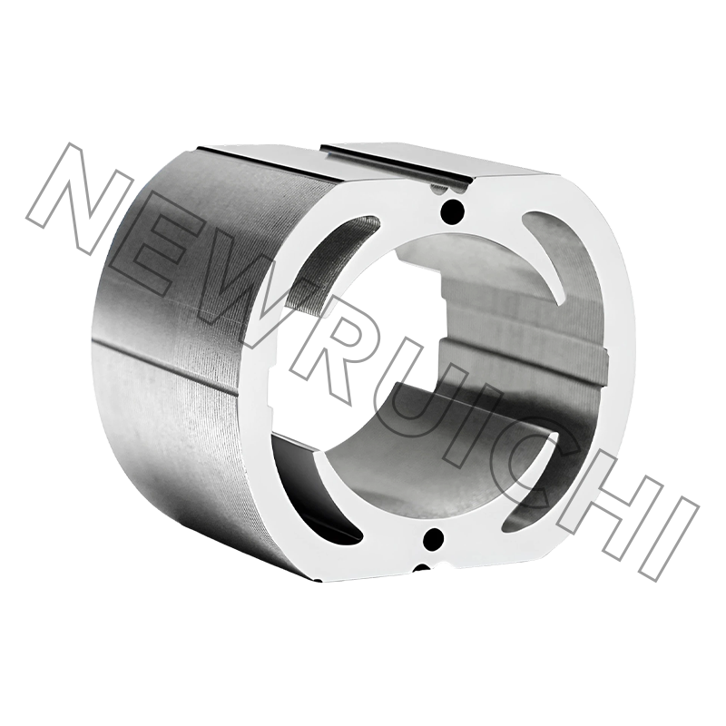
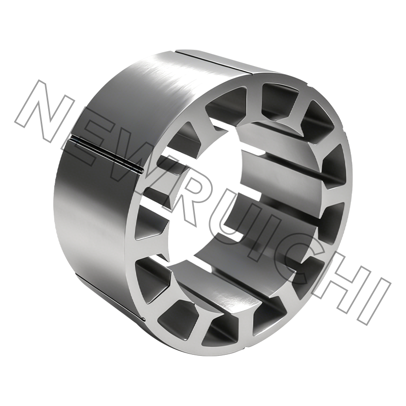
Stacking, Bonding, and Core Assembly: From Laminations to Functional Cores
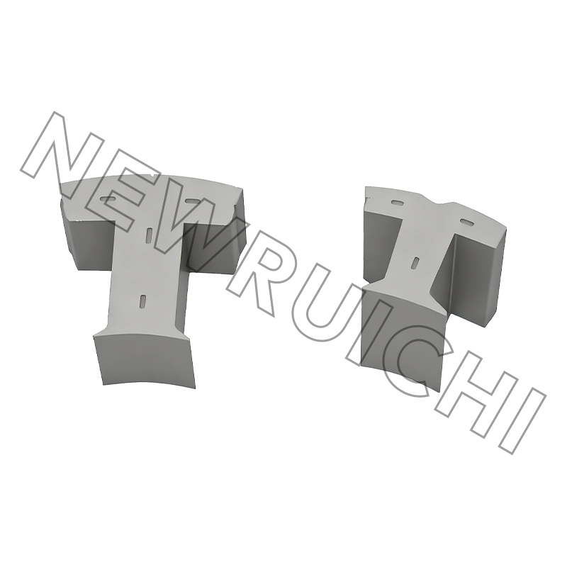
Individual servo motor stator and rotor laminations acquire their full functional value only when assembled into a coherent stacked core with consistent inter-laminar contact and precise axial alignment. The assembly method chosen affects mechanical integrity, magnetic performance, and suitability for downstream manufacturing processes including winding insertion and rotor balancing.
The primary stacking and bonding methods used for servo-grade cores are:
- Interlocking (self-clinching) — stamped dimples or tabs interlock adjacent laminations during stacking, providing mechanical cohesion without adhesive or fasteners; the most common method for high-volume production due to speed and cost efficiency
- Laser welding — axial weld beads applied along the outer diameter of the stacked core; produces a rigid assembly with good dimensional stability, though weld-induced stress can marginally increase local core loss in the affected zones
- Adhesive bonding (glued lamination stacks) — anaerobic or epoxy adhesives applied between lamination surfaces; eliminates mechanical stress from welding or interlocking, preserving the full magnetic properties of each lamination; preferred for ultra-low-noise and high-precision servo cores
- Through-bolt assembly — laminations aligned on a precision mandrel and clamped with through-bolts; used primarily for larger frame sizes where interlocking or welding is impractical
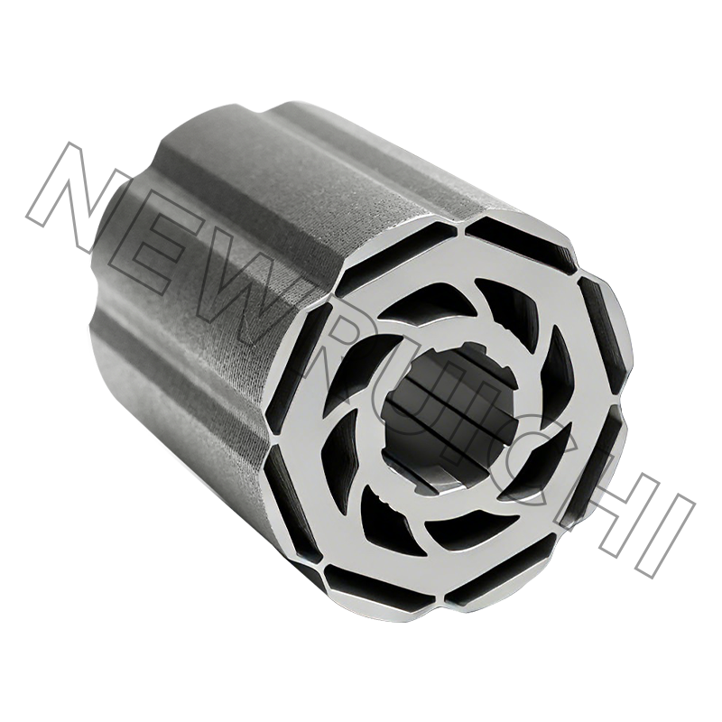
For rotor cores in permanent magnet servo motors, precise axial stacking alignment is particularly critical. Misalignment between the rotor lamination stack and the magnet mounting geometry introduces asymmetric flux paths that elevate both cogging torque and acoustic noise during operation.
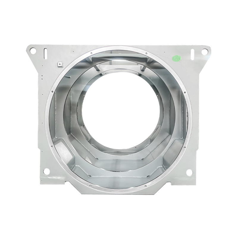
Customization Options for Servo Motor Lamination Geometry
Standard lamination geometries cover the most common servo motor frame sizes and pole–slot configurations, but many precision motion applications require customized lamination designs to meet specific performance, packaging, or integration requirements. Customization of lamination geometry is available across the following dimensions:
- Outer and inner diameter — tailored to specific motor frame dimensions or direct-drive integration constraints
- Slot shape and opening width — optimized for specific winding wire gauges, fill factors, and slot-leakage inductance targets
- Tooth tip geometry — chamfer angle and tip width adjusted to balance cogging torque reduction against flux density in the tooth tip region
- Rotor magnet pocket geometry — for interior permanent magnet (IPM) rotor designs, pocket shape determines flux barrier effectiveness and saliency ratio, both of which influence reluctance torque contribution and dynamic control bandwidth
- Stack length — adjusted to meet torque density targets within axial packaging constraints
Prototype tooling for custom lamination geometries can be produced at relatively low cost using wire EDM or laser cutting for initial validation, with progressive die tooling commissioned once the geometry is confirmed. This two-stage approach allows motor designers to iterate on lamination geometry without committing to high-volume tooling investment prematurely.
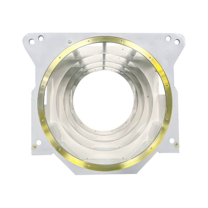
Performance Outcomes: What High-Quality Cores Deliver in Application
The cumulative effect of material selection, dimensional precision, optimized pole–slot design, and careful assembly is measurable at the system level. Servo motors built on high-quality motor stator cores and precision-stamped laminations consistently demonstrate the following performance characteristics compared to motors using lower-specification cores:
- Reduced torque ripple — enabling smoother motion profiles in robotic joints and linear positioning stages, with direct benefits for surface finish quality in machining applications and path accuracy in pick-and-place automation
- Lower operating temperature — reduced core loss translates to less heat generation at rated load, extending winding insulation life and allowing higher continuous duty cycles without derating
- Faster dynamic response — lower magnetic loss and higher permeability improve the motor's torque constant stability across the operating speed range, supporting tighter current loop bandwidths in the servo drive
- Reduced vibration and acoustic noise — controlled lamination flatness, smooth slot edges, and precise rotor balance suppress the mechanical excitation forces that generate audible noise, a requirement increasingly specified in medical, semiconductor, and collaborative robotics applications
- Consistent batch-to-batch performance — tight dimensional tolerances across production runs ensure that motor performance parameters remain within specification across the lifetime of a production program, reducing the need for individual motor calibration at the system integration stage
In high-cycle manufacturing environments where servo motors may execute tens of millions of positioning moves per year, these performance advantages compound over the operational life of the system — reducing energy consumption, extending maintenance intervals, and improving the total cost of ownership relative to motors built on lower-specification stator rotor core components.
আপনার ইমেল ঠিকানা প্রকাশ করা হবে না. প্রয়োজনীয় ক্ষেত্রগুলি * চিহ্নিত করা হয়েছে
![]() Email: [email protected]
Email: [email protected]
[email protected]
[email protected]
![]() টেলিফোন/ফোন:
+86-18861576796 +86-18261588866
টেলিফোন/ফোন:
+86-18861576796 +86-18261588866
+86-15061854509 +86-15305731515
কপিরাইট © Wuxi New Ruichi Technology Co., Ltd. / Wuxi Cailiang Machinery Co., Ltd. All rights reserved.
স্টেটর এবং রটার কোর প্রস্তুতকারক
